PWM 3wire IAC Questions

For discussing B&G MS-I/MS-II set-up and tuning of fuel parameters (including idle valves, etc.).
Forum rules
Read the manual to see if your question is answered there before posting. Many users will not reply if the answer is already available in the manual.

If your question is about troubleshooting, configuration, or tuning, you MUST include your processor type (MS-I or MS-II) and code version in your post. If your question is about PCB assembly or modifications, you must also include the main board version number (1.01, 2.2 or 3.0). For tuning/troubleshooting questions, please attached a datalog and your MSQ file to your post.

If you have questions about MS1/Extra or MS2/Extra code configuration or tuning, please post them at www.msextra.com Such questions posted here will be moved to: a temporary MSextra sub-forum, where they will be removed after 7 days

The full forum rules are here: Forum Rules, be sure to read them all regularly.
Post Reply
toms73novass
MegaSquirt Newbie
Posts: 2
Joined: Mon May 19, 2008 6:45 am

PWM 3wire IAC Questions

Post by toms73novass »

I am trying to figure out why my IAC valve is going full open, even though my settings in MS are set low.

I am using settings many with the same setup on a BMW e30 use with their 3 wire valves and have good results, however, not me....

I am trying to determine if my problems are hardware related.

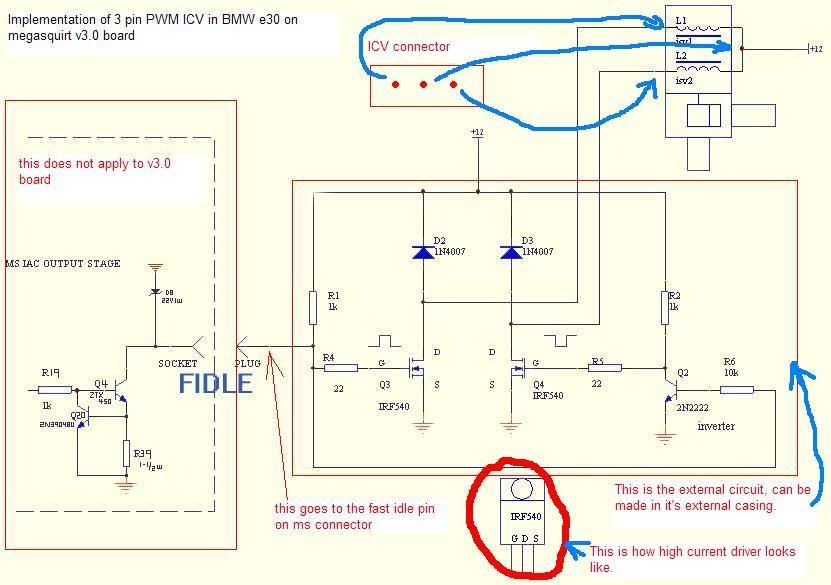
I am driving the valve with this circuit:

Image

I put a scope between the center pin and one of the outside pins and get this reading:

Image

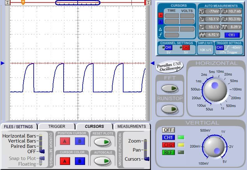
between the center pin and the other side I get a voltage reading of the same polarity as the scope reading above but there is no waveform, is this correct?

Or should I be getting a waveform signal on that side also?

Is there a way to trouble shoot the pwm circuit? I am quickly beginning to get close to getting over my head....


Any help would be much appreciated

Tom
turboy
MegaSquirt Newbie
Posts: 12
Joined: Sat Jan 27, 2007 10:54 am

Re: PWM 3wire IAC Questions

Post by turboy »

No, the otherside should show a mirrored wave form of the first one. Notice the little inverted wave form at the gate of the second powerfet. Trace the signal back to the gates of both power fets, they should be exact mirrors of each other.
toms73novass
MegaSquirt Newbie
Posts: 2
Joined: Mon May 19, 2008 6:45 am

Re: PWM 3wire IAC Questions

Post by toms73novass »

Thanks for the reply,

I was thinking that there was suppose to be signal on each side...

I tested back to Q3 and Q4 in the diagram. the G in the diagrams both have signal into them from MS ,
the D on q4 checks out with a signal , however, the D on q3 there is no signal.

My question now is:

Is there a way to test to see if the IRF is bad?
Could it be a bad diode in D2 that could cause the problem?
turboy
MegaSquirt Newbie
Posts: 12
Joined: Sat Jan 27, 2007 10:54 am

Re: PWM 3wire IAC Questions

Post by turboy »

Check, with an ohm meter if you have continuity between +12v of the valve to the "D" of Q3. If nothing is attached to the drain (D) then you'll see no signal.
Also measure the valve connections if you have the right pins.
To check out the circuit you can temporarly substitude the valve for a couple of resistors, e.g. 470ohm. Hook them up just as the coils shown in the schematic.
Post Reply