Incrementing rpm signal!?
Forum rules
Read the manual to see if your question is answered there before posting. Many users will not reply if the answer is already available in the manual.
If your question is about troubleshooting, configuration, or tuning, you MUST include your processor type (MS-I or MS-II) and code version in your post. If your question is about PCB assembly or modifications, you must also include the main board version number (1.01, 2.2 or 3.0). For tuning/troubleshooting questions, please attached a datalog and your MSQ file to your post.
If you have questions about MS1/Extra or MS2/Extra code configuration or tuning, please post them at www.msextra.com Such questions posted here will be moved to: a temporary MSextra sub-forum, where they will be removed after 7 days
The full forum rules are here: Forum Rules, be sure to read them all regularly.
-
The Benz Master
- Helpful Squirter
- Posts: 69
- Joined: Sun Aug 05, 2007 5:51 pm
- Location: Quebec, Canada
-
The Benz Master
- Helpful Squirter
- Posts: 69
- Joined: Sun Aug 05, 2007 5:51 pm
- Location: Quebec, Canada
-
The Benz Master
- Helpful Squirter
- Posts: 69
- Joined: Sun Aug 05, 2007 5:51 pm
- Location: Quebec, Canada
ok... so what should be the second output? is this a physical output or just software ?
I tried your missed pulse counter... it sits at zero 99% of time eccept when i let go the starter button it goes to -1 or -2... so my guess is that the gauge works.
output is still the same tho. Missing pulse with some second pulse at about 180deg

I tried your missed pulse counter... it sits at zero 99% of time eccept when i let go the starter button it goes to -1 or -2... so my guess is that the gauge works.
output is still the same tho. Missing pulse with some second pulse at about 180deg
-
The Benz Master
- Helpful Squirter
- Posts: 69
- Joined: Sun Aug 05, 2007 5:51 pm
- Location: Quebec, Canada
I tried your exact msq without touching it, with v2.881 code, on a stimulator on which I varied the rpm from 240 to 650 rpm back andd forth or letting it sit steady and I could see no missed outputs whatever The only way I could get a missed output was to accelerate or decelerate it so fast that it lost synch - but it never missed an output unless it lost synch (rpm=0, engine=0). I didn't look at the timing because I am now only interested in missed outputs - but it was consistent - it didn't move all over.
Yet, I agree that you are unlikely to be missing tach pulses because they would show up on the spare gauge. Do you have a stimulator you could try this on ?
Yet, I agree that you are unlikely to be missing tach pulses because they would show up on the spare gauge. Do you have a stimulator you could try this on ?
-
The Benz Master
- Helpful Squirter
- Posts: 69
- Joined: Sun Aug 05, 2007 5:51 pm
- Location: Quebec, Canada
No stimulator... the stim is my bike plugged to the computer. 
I tried MS2 extra code last night and no spark at all.... i've been looking at the extra forum for 4 hours searching of ATV's or any single cylinder working with MS and right now, i only found peoples having trouble with the long tooth and some others having weird tach output with MS2 processor.
I was thinking about shortening the tooth to 5 or 10 deg duration and if it does not work, ordering a MS1 chip !
This is just anoying cuz i paid 80$ to have an MS2 and now have to buy a MS1 too. And budjet is kinda DEAD right now. I was thinking using the same box for car and bike but...
I am beginning to suspect there may be something wrong with the processor. From the data it appears you are firing for a few seconds with some misses. What happens after that - will the engine just not start or does it get worse and quits firing altogether. I am just curious if this will run once you get past starting.
If you are willing to continue I can send you another processor to try.
If you are willing to continue I can send you another processor to try.
-
The Benz Master
- Helpful Squirter
- Posts: 69
- Joined: Sun Aug 05, 2007 5:51 pm
- Location: Quebec, Canada
the longest time i've had it to run is about 1 or 2 seconds... otherwise, it just fires about 3 times and kicks back... too much timing with 11:1 CR
a good chance that the starter of the bike has been designed with clutches to prevent starter damage when this hapens.
Will try new processor if you want to... PM sent
thanks
a good chance that the starter of the bike has been designed with clutches to prevent starter damage when this hapens.
Will try new processor if you want to... PM sent
thanks
If the reason it won't fire is because the timing is wrong, can't that be fixed by moving the trigger offset to get it in the right ballpark. If nothing else, you could use trigger rise mode with cranking rpm set to say 600 rpm and keep it running with a single advance. This obviously is not a final solution, but it would tell us whether the problem goes away at high rpm. What trigger rise does is fire the spark as soon as the tach input is received, so if there is any timing error it is because the mechanical advance (position of the VR sensor) is wrong..
-
The Benz Master
- Helpful Squirter
- Posts: 69
- Joined: Sun Aug 05, 2007 5:51 pm
- Location: Quebec, Canada
Trigger offset wont move anything even if cranking RPM is set to 50 !! And yes, mechanicaly, my trigger hapens at 60deg BTDT ... so trigger rise wont work. But i tought that the computer calculated a delay from the time it gets the trigger before fireing (more precise if trigger is 20-50 deg before spark than if it's exactly at tdc (350deg before spark)) so it should work fairly well right now but it semms that it doesn work like this somehow !
I will modify the trigger as soon as i have time (3 or 4 days) now 60 deg long from 60 btdc to TDC... so should i leave only a small tooth at tdc or should i leave one 60deg before TDC?
It's not a high reeving four stroke like the CRF 450's and the Yams so engine internals weight much more and has a 7200 rpm redline... engine acceleration speed should be fairly less intense/problematic but it's still a 650 1 cyl at 11:1 CR... not sure how precise it has to be to work properly.?
thanks
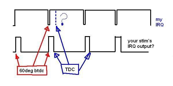
Your wheel looks perfect for trigger return mode. Going by your picture I assume the trailing edge labelled TDC means that when this edge is at the VR sensor the engine is at TDC. When the leading edge is under the sensor, the engine is 60 deg btdc. If you want the engine to fire at around 10-15 deg btdc during cranking, then you could take off the width of 10-15 deg from the TDC edge, so now the sensor will trigger 10-15 deg earlier (btdc). In trigger return mode it will fire immediately at this point - the falling edge - as long as rpm is below cranking rpm. There is no error. Then when above cranking, it will use the table advance and will only detect the rising edge, then wait for 60 deg - table adv, then spark. You set trigger offset = +60 deg, which tells the processor that when the sensor detects the leading/rising edge, the engine is 60 deg btdc.The Benz Master wrote:
I will modify the trigger as soon as i have time (3 or 4 days) now 60 deg long from 60 btdc to TDC... so should i leave only a small tooth at tdc or should i leave one 60deg before TDC?
thanks
Note that in trigger return mode, there is nothing to tell the processor that the cranking position is 10-15 deg btdc, so during cranking only the MT gauge will show the advance as 60 deg btdc (= trigger offset). Just ignore this, the scope or a timing light should show it is at 10-15deg btdc.
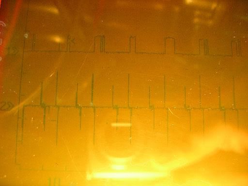
Last night I checked the timing using your msq, but with trigger offset set to +60 deg. What this is saying is that with your wheel being detected on the leading/ rising edge (the one marked 60 deg) the engine is at 60 deg BTDC. ( A -60 would mean ATDC and should (must) be used with dual spark mo0de but generally not with non-dual spark. I ran your msq with only this change with a 444 rpm signal and got the following:
---|-------------------~------------------------------------------------------|-----------------------Spark------|
---|-------------------~------------------------------------------------------|-----------------------@12deg---|
---|-------------------~------------------------------------------------------|--------------------------|---------|
---|--------------------~-----------------------------------------------------|<-----60deg/22.5ms---------->|
--VR1----------------~-----------------------------------------------------VR2-------------------------------TDC
---|<----------------~-----360deg/135ms------------------------------>|
In this, VR1, VR2 are 2 sensor detections, they may be a rising or falling edge depending on the exact physical setup. These are separated by 360 deg for 1 cyl wasted spark. I measured 135 ms for 444 rpm - exactly as it should be. From here on you can convert deg to time in ms by ms = (deg/ 360) * 135 ms, so 60 deg is 22.5 ms and 12 deg is 4.5 ms. 12 deg is the table advance and it occurs at exactly the right time. Again the Spark is the rising or falling edge depending on the physical setup. Remember the edge is what the processor sees - it has no way of knowing if you may or may not have inverted things by putting FET drivers after the processor pin. On the scope all you will see are the VR1, VR2 and Spark changes, you have to figure out where TDC is by going 60 deg to the right of the VR edge. Then you back up by the 12 deg advance.
If things don't come out like this, then play with changing the edge detection polarities. Before doing anything to your wheel you should verify you can get this picture. That is why a stimulator is so handy.
-
The Benz Master
- Helpful Squirter
- Posts: 69
- Joined: Sun Aug 05, 2007 5:51 pm
- Location: Quebec, Canada
Ok, there was this slight improvement i wanted to do on hardware... cant stand to have to open the box open every time i want to change some settings...
So now i'll be able to update code, and change crank sensor without opening the box. And changing processor will only need removing top cover.
Speaking of processor, the only diference on V3 board for MS1 or MS2 use is the 12v supply on JS9 and b/l is on the motherboard instead of being on the processor right? i dont want to ruin the processor before solving my problem !! Right now the MS1-MS2 switch replaces the jumper wire between s12c and JS9.
So now i'll be able to update code, and change crank sensor without opening the box. And changing processor will only need removing top cover.
Speaking of processor, the only diference on V3 board for MS1 or MS2 use is the 12v supply on JS9 and b/l is on the motherboard instead of being on the processor right? i dont want to ruin the processor before solving my problem
-
The Benz Master
- Helpful Squirter
- Posts: 69
- Joined: Sun Aug 05, 2007 5:51 pm
- Location: Quebec, Canada
Done some testing with trigger return as cranking trigger and i found something so obvious....
Wether i have the ignition on trigger return or trigge rrise, the result is exactly the same cuz this is the output i get from VR circuit to the processor... trigger rise and trigger return are exactly at the same place... i guess your stim does an effective 60 deg wide tooth... it would be perfect if i used a hall sensor tho. But i still get one out of 2 outputs... did not change processors yet, i'll look into this the next time i do some tests.
Wether i have the ignition on trigger return or trigge rrise, the result is exactly the same cuz this is the output i get from VR circuit to the processor... trigger rise and trigger return are exactly at the same place... i guess your stim does an effective 60 deg wide tooth... it would be perfect if i used a hall sensor tho. But i still get one out of 2 outputs... did not change processors yet, i'll look into this the next time i do some tests.
-
The Benz Master
- Helpful Squirter
- Posts: 69
- Joined: Sun Aug 05, 2007 5:51 pm
- Location: Quebec, Canada
I tried the new MS2 processor.... i get timing exactly where it should but there is some extra sparks sometimes.
i've learned how to measure time with my scope and found out that the mean cranking RPM is 280 for intake/compression strokes and 480 for explosion/exhaust strokes. this is a 72% diference... so i upped the next pulse tolerance thinking that this is what was causing the problem but no (the extra pulses i get are exactly 125ms from one of the neighboring pulses... 125 ms being exactly the shortest interval i get between 2 trigger events.... looks like quite a coincidence)
I will retry this exact same MSQ with my processor tomorow to see the diference. From memory, i was missing some pulses and got some extra ones and timing was just off with my proc and with this one i only get some extras and get good timing.
Now if it was'nt for these extra pulses, it should be working fine with this set-up.
You do not have the required permissions to view the files attached to this post.
Let us know if the old ms2 processor gives a different result than the new one.
As far as the extra pulses, this may be a result of the drastic change in rpm from intake to compression strokes. Since you have given me good numbers (280, 480 rpm) I will try to simulate this iin my signal generating code if I can. However, increasing your pulse tolerance should prevent the problem. There are 3 tolerances: I see from the msq that you have set the cranking and after start tolerances to 95%, which is good, but the normal pulse tol is 60%. That would be fine except your cranking rpm is only 100, so it will immediately go to after start and possibly to normal running very quickly, depending on conditions. For test purposes set the normal tolerance to 95 % also. What may be happening is that after an explosion the processor sees a short time, then a long time. It may interpret this as a missing pulse and shove another virtual one in there - which would generate and extra output. This should not happen with the high pulse tolerances. However, if I can't easily duplicate your IRQ signal, I can send you test code that will never put in any extra IRQ pulses or remove any pulses it thinks are false. We can see if this avoids the extra output pulses.
As far as the extra pulses, this may be a result of the drastic change in rpm from intake to compression strokes. Since you have given me good numbers (280, 480 rpm) I will try to simulate this iin my signal generating code if I can. However, increasing your pulse tolerance should prevent the problem. There are 3 tolerances: I see from the msq that you have set the cranking and after start tolerances to 95%, which is good, but the normal pulse tol is 60%. That would be fine except your cranking rpm is only 100, so it will immediately go to after start and possibly to normal running very quickly, depending on conditions. For test purposes set the normal tolerance to 95 % also. What may be happening is that after an explosion the processor sees a short time, then a long time. It may interpret this as a missing pulse and shove another virtual one in there - which would generate and extra output. This should not happen with the high pulse tolerances. However, if I can't easily duplicate your IRQ signal, I can send you test code that will never put in any extra IRQ pulses or remove any pulses it thinks are false. We can see if this avoids the extra output pulses.