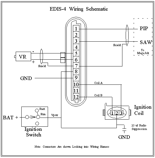
well, im in the middle of wiring up EDIS right now, and i think ive run into a problem with the wiring on the EDIS module and the coil pack harness. anyways, pin 10 on the module is supposed to go with pin 1 on the coil pack and pin 12 is supposed to go with pin 3.
anyways, the problem i have here is that the wiring on pin 10 on the EDIS module has the exact same wire color as pin 3, and pin 12 has the exact same color wiring at pin 1.
should i match up the colors or match up what the diagram says?
EDIS wiring loom
Forum rules
Read the manual to see if your question is answered there before posting. Many users will not reply if the answer is already available in the manual.
If your question is about troubleshooting, configuration, or tuning, you MUST include your processor type (MS-I or MS-II) and code version in your post. If your question is about PCB assembly or modifications, you must also include the main board version number (1.01, 2.2 or 3.0).
If you have questions about MS1/Extra or MS2/Extra code configuration or tuning, please post them at www.msextra.com Such questions posted here will be moved to: a temporary MSextra sub-forum, where they will be removed after 7 days
The full forum rules are here: Forum Rules, be sure to read them all regularly.
-
MegaScott
Never go by the colors. Go by the pin numbers.
One thing I've noticed when wiring up the ford EDIS coils is that the pin location on the connector is opposite of the coils physical location, at least on the EDIS4 coils.
Also if you look around the web there are a few different schematics of EDIS out there, some of them are wrong....you can't trust the internet all the time. Go by what it shows in the Megamanual, I know it works.
-
A20Accord
-
MegaScott
If you find a problem with the Megamanual let the admins know and it will get fixed, though the information for EDIS is pretty old and reliable AFAIK.A20Accord wrote:ill go by the manual because its been a proven method that works. in the event it the wires are in fact switched, will this create a problem?
-
A20Accord
ive apparently stumbled across these 2 diagrams from megasquirt and megajolt websites.
this one shows what the wiring would look like if i matched up the colors on the harness.
this one shows what it would look like if the colors arent matched up
hard to say which one is correct mainly cause both the sites are dedicated to megasquirt. which one do you suggest i use?
this one shows what the wiring would look like if i matched up the colors on the harness.
this one shows what it would look like if the colors arent matched up
hard to say which one is correct mainly cause both the sites are dedicated to megasquirt. which one do you suggest i use?
-
A20Accord
-
FixItAgainTony
- Helpful Squirter
- Posts: 82
- Joined: Thu Feb 03, 2005 1:09 pm
Given that I just got done doing this 10 minutes ago, I'll chime in.
The top drawing looks a little better to me, but unless you are concerned with having the numbers on the coil match the numbers on the spark plugs, it does not matter.
EDIS Pin 10 = coil A which fires cyclinders 1&4. The easiest way to get it right is to look at the three wires going into the coil pack when the connector is installed. The center wire is power, the wire on the left controls the coil on the left, the wire on the right controls the coil on the right. ie - wire closest to the coil fires that coil.
I set mine up to the bottom drawing, and had to swap the wires. Not a big deal.
MegaScott's warning on the wire colors is very valid. I have two connectors for the Vr sensor that are the same in every way, except that the grey and blue wires coming out of the connector are in different locations.
- Charles.
Fiat - A great car for those who like to walk.
-
A20Accord
-
FixItAgainTony
- Helpful Squirter
- Posts: 82
- Joined: Thu Feb 03, 2005 1:09 pm
search on EDIS and polarity:
The last reply in this thread gets the polarity right:
viewtopic.php?p=191148&highlight=edis++polarity#191148
Same thing here:
viewtopic.php?p=165610&highlight=edis++polarity#165610
Note that I have a connector to the VR that has grey + & blue negative.
I have another connector that looks the same, but has blue as + & grey as negative.
MegaScott's advice is dead on.
You can do the check with a digital meter. It is probably easist to set the meter to its lowest voltage setting (mV). Attach the steel and then pull it away and observe a brief negative voltage. Positive as steel approaches, negative as steel pulls away. Because of the sampling on a digital meter, it will take a few tries to make sure the results are consistent. I have done this both style of meters. If you are working with an autoranging digital meter, It will be a bit harder.
- Charles.
The last reply in this thread gets the polarity right:
viewtopic.php?p=191148&highlight=edis++polarity#191148
Same thing here:
viewtopic.php?p=165610&highlight=edis++polarity#165610
Note that I have a connector to the VR that has grey + & blue negative.
I have another connector that looks the same, but has blue as + & grey as negative.
MegaScott's advice is dead on.
You can do the check with a digital meter. It is probably easist to set the meter to its lowest voltage setting (mV). Attach the steel and then pull it away and observe a brief negative voltage. Positive as steel approaches, negative as steel pulls away. Because of the sampling on a digital meter, it will take a few tries to make sure the results are consistent. I have done this both style of meters. If you are working with an autoranging digital meter, It will be a bit harder.
I think the quote above is EDIS manual worthy... it will always work and save people a little trouble.From Jim:
Attach an analog multi-meter to VR sensor and set to mVolts. (DC)
Let the sensor snap to some steel object , If the voltage goes up
that is like an advancing tooth ,
then you have the DMM on respective + and - wires.
[edit] ** On Jim's:
Blue is Plus
Grey is Minus
** I have one like this, and another that is the opposite [/edit]
If voltage goes negative then you are backwards.
This also tests the VR sensor (easy to do at junk yard).
Of course the voltage will go opposite when you pull the sensor off the metal
- Charles.
Fiat - A great car for those who like to walk.